Last update 2007-10-15
Reverse-Engineering the Saab 9-3 Powertrain Bus (P-BUS)
This document describes reverse-engineering the Powertrain Bus (P-Bus) on my Saab 9-3 (MY2001) car. P-Bus is an
internal bus that connects together the Engine Control Unit (Trionic 7), ABS / Traction Control (if installed)
and Main Instrument panel. The bus is based on the Controller Area Network (CAN) standard.
Table of Contents
After watching the communication with an oscilloscope I figured out that the CAN bus speed is 500 kbit/s
(bit time is 2 µs). Figure 1 shows a screen grab from the oscilloscope while connected to the P+ and P- signals.
You can clearly see that the signal is differential.
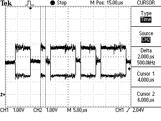 Figure 1. P+ and
P- signals viewed with an oscilloscope
Figure 1. P+ and
P- signals viewed with an oscilloscope
All the messages on the bus have eight (8) data bytes even if it wouldn't be necessary. I'm guessing this
simplifies response time calculations and the software that receives and decodes the messages.
- CAN 2.0A (11-bit identifiers)
- Bus speed 500 kbit/s
- Timing register settings BTR0 0x00, BTR1 0x1C
I monitored the bus with Peak Systems PCAN-View software. You can see in Figure 2 the messages sent to the bus
by the Trionic by itself (not connected to anything).
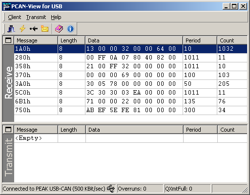 Figure 2.
PCAN-View showing messages sent by the Trionic ECU
Figure 2.
PCAN-View showing messages sent by the Trionic ECU
Message is sent with an interval of 10 milliseconds. The ENGSTOPPED bit in the STATUS byte indicates if the engine
is running or stopped. Engine RPM is shown as a 16-bit value (RPM1 and RPM0). MAP shows the Manifold Absolute
Pressure in kilopascals. THROTTLE byte is the throttle pedal position, with a value range of 0...100 percent
(0...64hex). MAF is the reading from Mass Air Flow sensor.
| ID |
Byte 0 |
Byte 1 |
Byte 2 |
Byte 3 |
Byte 4 |
Byte 5 |
Byte 6 |
Byte 7 |
| 1A0h |
STATUS |
RPM1 |
RPM0 |
MAP |
|
THROTTLE |
- |
MAF |
| Byte |
Bit 7 |
Bit 6 |
Bit 5 |
Bit 4 |
Bit 3 |
Bit 2 |
Bit 1 |
Bit 0 |
| STATUS |
CHANGED |
- |
- |
- |
ENGSTOPPED |
- |
- |
- |
Message is sent with an interval of 20 milliseconds. Vehicle speed is indicated by the 16-bit value (bytes SPEED1
and SPEED0). You will need to divide the value by 10 to get the right scaling, kilometers per hour. The byte 3
seems to be 80h all the time.
| ID |
Byte 0 |
Byte 1 |
Byte 2 |
Byte 3 |
Byte 4 |
Byte 5 |
Byte 6 |
Byte 7 |
| 2F0h |
- |
SPEED1 |
SPEED0 |
? |
- |
- |
- |
- |
Message is sent with an interval of 1 second and if a value changes. The most significant bit of the first byte
(byte 0) is set if information has changed from the last message. The GEAR byte is 02h if the reverse gear
selected, otherwise the byte is FFh. When the brake pedal is pressed lightly only bit 1 of the PEDAL byte will be
set. Normal braking will set bits 1, 3 and 4. The BRAKE/CLUTCH bit will also be set if the clutch is pressed. The
ACTIVE bit in the CRUISE byte is set when cruise control has been activated. The ?? byte indicates that the engine
is running or something like that (needs closer inspection).
| ID |
Byte 0 |
Byte 1 |
Byte 2 |
Byte 3 |
Byte 4 |
Byte 5 |
Byte 6 |
Byte 7 |
| 280h |
STATE |
GEAR |
PEDAL |
- |
CRUISE |
?? |
- |
- |
| Byte |
Bit 7 |
Bit 6 |
Bit 5 |
Bit 4 |
Bit 3 |
Bit 2 |
Bit 1 |
Bit 0 |
| STATE |
CHANGED |
- |
- |
- |
- |
- |
- |
- |
| PEDAL |
- |
- |
KICKDOWN |
BRAKE |
BRAKE/CLUTCH |
- |
BRAKE |
- |
| CRUISE |
- |
- |
ACTIVE |
- |
- |
- |
- |
- |
Example message:
80 FF 0A 00 00 C0 82 00
Information has changed from the last message, reverse gear is not selected, brake pedal has been pressed and the
engine is running (?).
A group of three messages are sent with an interval of 1 second and if a value changes. Messages are sent with
about 10 milliseconds apart. The CHANGED bit in the ROW byte will be set if information changes. The two bits ORD0
and ORD1 in the ORDER byte are for sequence numbering. A new message group starts with the NEW bit set and both
ORD0 and ORD1 bits. On the second message the NEW and ORD1 bits are cleared and the third message has also the
ORD0 bit cleared. So the ORDER byte will be 42, 01 and 00 for the three sequential messages. The ROW byte tells to
which row of the SID the text will be displayed on. The byte can have a value of 2 or 1, but in these audio text
messages the row number is always 2. The TEXT4...TEXT0 bytes are plain ASCII coded characters that will be
displayed on the SID.
Note that the last message will contain only one normal character in the TEXT4 byte. The TEXT3 byte should
contain a integer value that will be shown as a small number to indicate the selected radio station number. The
last TEXT2...TEXT0 bytes are always zeros.
| ID |
Byte 0 |
Byte 1 |
Byte 2 |
Byte 3 |
Byte 4 |
Byte 5 |
Byte 6 |
Byte 7 |
| 338h |
ORDER |
- |
ROW |
TEXT4 |
TEXT3 |
TEXT2 |
TEXT1 |
TEXT0 |
| Byte |
Bit 7 |
Bit 6 |
Bit 5 |
Bit 4 |
Bit 3 |
Bit 2 |
Bit 1 |
Bit 0 |
| ORDER |
- |
NEW |
- |
- |
- |
- |
ORD1 |
ORD0 |
| ROW |
CHANGED |
- |
- |
- |
- |
- |
ROW1 |
ROW0 |
Example message group:
42 96 02 55 31 20 4B 49 U 1 _ K I
01 96 02 53 53 20 46 4D S S _ F M
00 96 02 20 01 00 00 00 _ 1
The text "U1 KISS FM " will be displayed on the SID display and the radio station number is 1.
Message is sent with an interval of 1 second. The normal value of byte STATUS is FFh. When a 338h Trionic to SID
text message group is sent, the STATUS byte is changed to 04h and immediately after that to 05h for the duration
of the messages. After the 338h messages, the status byte returns to FFh. Byte UNKNOWN1 is 00h when STATUS is FFh
and 01h when STATUS is 05h. UNKNOWN2 byte also changes from 08h (STATUS is FFh) to 12h (STATUS is 05h).
| ID |
Byte 0 |
Byte 1 |
Byte 2 |
Byte 3 |
Byte 4 |
Byte 5 |
Byte 6 |
Byte 7 |
| 358h |
1F |
UNKNOWN1 |
STATUS |
UNKNOWN2 |
00 |
00 |
00 |
00 |
Example message:
1F 01 05 12 00 00 00 00
.
.
1F 00 05 08 00 00 00 00
First line: requesting SID to display text provided with message 338h. Second line: SID should not display Trionic
text.
Message is sent with an interval of 100 milliseconds. The 24-bit value (comprised of MIL2, MIL1 and MIL0) shows
the length that has been travelled since the engine was started. You will need to divide the value by 100 to get
right scaling (the value's unit is meters). The value 000069h seems to tell that you haven't moved yet.
| ID |
Byte 0 |
Byte 1 |
Byte 2 |
Byte 3 |
Byte 4 |
Byte 5 |
Byte 6 |
Byte 7 |
| 370h |
STATUS |
MIL2 |
MIL1 |
MIL0 |
- |
- |
- |
- |
Example message:
00 02 D1 50 00 00 00 00
You have travelled 1 846,56 meters.
Message is sent with an interval of 55 milliseconds. Vehicle speed is indicated by the 16-bit value SPEED (bytes
SPEED1 and SPEED0). You must divide the 16-bit value by 10 to get the value in kilometers per hour.
| ID |
Byte 0 |
Byte 1 |
Byte 2 |
Byte 3 |
Byte 4 |
Byte 5 |
Byte 6 |
Byte 7 |
| 3A0h |
- |
- |
- |
SPEED1 |
SPEED0 |
- |
- |
- |
Message is sent with an interval of 1 second and if a value changes. The most significant bit of the first byte
(byte 0) is set if information has changed from the last message. LIGHT byte indicates the park and daylight
head-lights with the PARK and DAY bits. When ignition signal is off, the OFF bit is set in the LIGHT byte. The ??
byte is 20h when ignition signal is off and B8h when the signal is on.
| ID |
Byte 0 |
Byte 1 |
Byte 2 |
Byte 3 |
Byte 4 |
Byte 5 |
Byte 6 |
Byte 7 |
| 3B0h |
STATE |
LIGHT |
- |
?? |
- |
- |
- |
- |
| Byte |
Bit 7 |
Bit 6 |
Bit 5 |
Bit 4 |
Bit 3 |
Bit 2 |
Bit 1 |
Bit 0 |
| STATE |
CHANGED |
- |
- |
- |
- |
- |
- |
- |
| LIGHT |
- |
1 |
1 |
1 |
OFF |
1 |
PARK |
DAY |
| ?? |
- |
- |
- |
- |
- |
- |
- |
- |
Example message:
00 76 74 B8 00 00 00 00
Information has not changed from the last message and the head-lights are in park mode.
Message is sent with an interval of 1 second and if a value changes. The most significant bit of the first byte
(byte 0) is set if information has changed from the last message. The GEAR byte indicates in what state the
gearbox is. Value 05h means Forward, value 03h Neutral and value 02h Reverse. The GEAR SHIFT byte tells in what
position the gear shift is. Value 01h means Park, value 02h Reverse, value 03h Neutral, value 04h Drive, value
08h "limit to 4", value 07h "limit to 3" and value 06h "low speed gear".
Information provided by Magnus Lirell.
| ID |
Byte 0 |
Byte 1 |
Byte 2 |
Byte 3 |
Byte 4 |
Byte 5 |
Byte 6 |
Byte 7 |
| 3E0h |
STATE |
GEARBOX |
GEAR SHIFT |
MODE1 |
Adaptation? |
MODE2 |
- |
- |
| Byte |
Bit 7 |
Bit 6 |
Bit 5 |
Bit 4 |
Bit 3 |
Bit 2 |
Bit 1 |
Bit 0 |
| STATE |
CHANGED |
- |
- |
- |
- |
- |
- |
- |
| GEARBOX |
- |
- |
- |
- |
- |
- |
- |
- |
| GEAR SHIFT |
- |
- |
- |
- |
POS |
POS |
POS |
POS |
| MODE2 |
- |
- |
- |
- |
- |
- |
SPORT/WINTER |
SPORT/WINTER |
Example message:
00 00 00 00 00 00 00 00
Example text...
Message is sent with an interval of 1 second. The ACCON bit in the ACC byte tells if the ACC (Automatic Climate
Control) is turned on. When the bit is set, the ACC is on and when the bit is cleared the ACC has been turned off.
The ACREQ bit indicates A/C request from DICE (not sure, a guess at the moment...). ACPRESS byte shows the A/C
Pressure (unit is bar).
| ID |
Byte 0 |
Byte 1 |
Byte 2 |
Byte 3 |
Byte 4 |
Byte 5 |
Byte 6 |
Byte 7 |
| 530h |
- |
ACC |
- |
ACPRESS |
- |
- |
- |
- |
| Byte |
Bit 7 |
Bit 6 |
Bit 5 |
Bit 4 |
Bit 3 |
Bit 2 |
Bit 1 |
Bit 0 |
| ACC |
- |
- |
- |
- |
ACREQ? |
ACCON |
- |
- |
Example message:
00 00 00 00 00 00 00 00
Text here.
Message is sent with an interval of 1 second. Temperature is reported with a 8-bit byte. In order to get the
correct coolant temperature, the value must be subtracted with 40. This is done to encode negative temperatures.
So a value of 58 (3Ah) is in fact +18 degrees Celsius and on the other hand a value of 29 (1Dh) would give an
temperature of -11 degrees Celsius. The 16-bit value combined from PRES1 and PRES0 gives the Ambient air pressure
in hehtopascals [hPA].
| ID |
Byte 0 |
Byte 1 |
Byte 2 |
Byte 3 |
Byte 4 |
Byte 5 |
Byte 6 |
Byte 7 |
| 5C0h |
- |
COOLANT |
COOLANT |
PRES1 |
PRES0 |
- |
- |
- |
Example message:
00 6A 6A 03 F9 00 00 00
Coolant temperature is 66 degrees Celsius and air pressure is 1017 hPa.
Message is sent with an interval of 1 second.
| ID |
Byte 0 |
Byte 1 |
Byte 2 |
Byte 3 |
Byte 4 |
Byte 5 |
Byte 6 |
Byte 7 |
| 631h |
- |
- |
- |
- |
- |
- |
- |
- |
Message is sent with an interval of 1 second.
| ID |
Byte 0 |
Byte 1 |
Byte 2 |
Byte 3 |
Byte 4 |
Byte 5 |
Byte 6 |
Byte 7 |
| 6B1h |
- |
- |
- |
- |
- |
- |
- |
- |
Message is sent with an interval of 1 second.
| ID |
Byte 0 |
Byte 1 |
Byte 2 |
Byte 3 |
Byte 4 |
Byte 5 |
Byte 6 |
Byte 7 |
| 6B2h |
- |
- |
- |
- |
- |
- |
- |
- |
Messages are sent when the car key is turned to ignition on. This leads me to believe that these two messages
are somehow connected to the anti-theft system. The CODE bytes seem to have random numbers in them that change
after a successful "handshake".
The 750h message is sent first and after about 20 ms the 740h message is sent. The "reply" can contain zeroed
CODE bytes and the STATUS byte as FFh. In that case after about 190 ms the same 750h message is repeated. The
second 740h "reply" seems to be always ok, since it has something in the CODE bytes and the STATUS byte is 55h.
| ID |
Byte 0 |
Byte 1 |
Byte 2 |
Byte 3 |
Byte 4 |
Byte 5 |
Byte 6 |
Byte 7 |
| 740h |
CODE4? |
CODE3? |
CODE2? |
CODE1? |
CODE0? |
STATUS |
00 |
00 |
| 750h |
CODE4? |
CODE3? |
CODE2? |
CODE1? |
CODE0? |
00 |
00 |
00 |
Example messages:
750 4F C3 11 2A FA 00 00 00
740 FE 91 EA 5C CD 55 00 00
750 7E EE 9B FF 6E 00 00 00
740 00 00 00 00 00 FF 00 00
750 7E EE 9B FF 6E 00 00 00
740 58 67 92 77 4F 55 00 00
750 21 E9 FF F8 4A 00 00 00
740 00 00 00 00 00 FF 00 00
750 21 E9 FF F8 4A 00 00 00
740 2C DB 4A 7E 49 55 00 00
750 14 20 42 C7 C3 00 00 00
740 00 00 00 00 00 FF 00 00
750 14 20 42 C7 C3 00 00 00
740 04 B9 29 D2 03 55 00 00
In this example the first column indicates the message ID. These are real-world examples of the messages. If
someone figures out how these messages work, it could mean that the anti-theft mechanism could be bypassed.
If you have comments, questions, new decoded I-Bus/P-Bus messages or would like to share information about your
own Saab I-Bus project, you're free to email me at firstname.surname@gmail.com.
Note that you have to fix the email address, the one in the link is invalid (firstname = tomi and surname =
liljemark). It may take me sometime to answer, but I'll try to answer everyone.
- Wikipedia, the free encyclopedia: Controller
Area Network (HTML document)
- Nilsson, Staffan: Controller
Area Network - CAN Information (HTML document)
- Can in Automation CiA: CAN physical
layer (HTML document)
- Kvaser AB: The CAN
Protocol (HTML document)
- Kvaser AB: CAN
Physical Layers (HTML document)
- Lawicel: CAN232 Manual (PDF
document)