Reverse-Engineering the Saab 9-3 Instrumentation Bus (I-BUS)
Preface
This document describes reverse-engineering the Instrumentation Bus (I-Bus) on my Saab 9-3 (MY2001) car. I-Bus is an internal bus that connects together instruments such as the radio, automatic climate control and the Saab Information Display. For example the integrated radio doesn't have a display, so it sends messages via I-Bus to the Saab Information Display to show radio channel frequency, RDS channel name and so on. The bus is based on the Controller Area Network (CAN) standard.
I'll first explain what CAN is, but shortly since there are many other sites covering CAN itself. In the Saab Instrumentation Bus section I'll describe how I reverse-engineered the I-Bus, and what messages I've decoded this far. The last section covers a Visual Basic .NET example program that I wrote to display information from the bus in an understandable form.
I've written this document mainly because I couldn't find almost any information about the I-Bus or about car CAN buses in general for that matter. The only site describing CAN bus reverse-engineering I could find was Attila Vass' site The Hybrid 2004 Toyota Prius - My CAN Project. Big thanks to him for sharing the information and inspiring others (like me) to do the same. I'd also like to thank Tobias Björkman, Carl Levine (AudioTroll), Magnus Lirell, George Kozak, David Goncalves and many more for emailing me about my project and unknowingly pushing me to create these pages.
Table of Contents
- Preface
- Controller Area Network (CAN)
- Saab Instrumentation Bus
- Discovered
message information
- 220h - Trionic data initialization
- 238h - Trionic data initialization reply
- 240h - Trionic data query
- 258h - Trionic data query reply
- 266h - Trionic reply acknowledgement
- 280h - Pedals, reverse gear
- 290h - Steering wheel and SID buttons
- 320h - Doors, central locking and seat belts
- 328h - SID audio text
- 32Ch - ACC to SID text
- 32Fh - TWICE to SID text
- 337h - SPA to SID text
- 348h - SID audio text control
- 34Ch - ACC to SID text control
- 34Fh - TWICE to SID text control
- 357h - SPA to SID text control
- 368h - SID text priority
- 380h - Audio RDS status
- 3B0h - Head lights
- 3C0h - CD Changer control
- 3C8h - CD Changer information
- 3E0h - Automatic Gearbox
- 410h - Light dimmer and light sensor
- 439h - SPA distance
- 430h - SID beep request
- 460h - Engine rpm and speed
- 4A0h - Steering wheel, Vehicle Identification Number
- 520h - ACC, inside temperature
- 590h - Position Seat Memory
- 5C0h - Coolant temperature, air pressure
- 630h - Fuel usage
- 640h - Mileage
- 6A1h - Audio head unit
- 6A2h - CD changer
- 720h - RDS time
- 730h - Clock
- 740h 750h - Security
- 7A0h - Outside temperature
- Example program
- OBD2SID - OBD-II information to SID
- SaabCanLogger
- Comments, questions?
- References
Controller Area Network (CAN)
History
Controller Area Network (CAN) was developed by Robert Bosch GmbH in the 1980's. It was intended for noisy operating environments and had a (relatively) high data transfer rate. First applications were electronic control units in cars, but nowadays CAN is used also in industrial control applications. [1]. Maximum data transfer rate is 1 Mbit/s with short network length (40 meters). Decreasing the data transfer rate increases the maximum network length, up to 6 kilometers with 10 kbit/s speed. [2].
Standards
There are several CAN standards that define the physical layer and the application layer. The most used physical layer standard is the ISO 11898-2 (CAN high-speed). For special applications the ISO 11898-3 (CAN fault-tolerant low-speed) standard specifies how to better withstand noise, short circuits and open circuits. [3]. The Saab I-Bus uses ISO 11898-2 physical CAN standard.
Physical layer
CAN is a broadcast type bus, meaning that every device connected to the bus can receive all messages that have been transmitted on the bus. CAN transceivers implement filters to receive only messages with specified identifiers. A transceiver sends a bit to the bus as either dominant or recessive. If one or more transceivers send a recessive bit to the bus, the bus state will be recessive. But if a single dominant bit is sent to the bus, the bus will be in a dominant state. [4].
CAN protocol
Messages on a CAN bus are sent within CAN frames that include an identifier number, number of data bytes, the actual data payload and checksum. The identifier usually specifies what data the frame contains. It is up to the application layer (open standard or proprietary company standard) to define what information is stored in each used identifier. The Saab I-Bus doesn't seem to follow any open standard (that I know of).
There are two CAN frame formats: the basic frame (referred as CAN2.0A) and the extended frame (referred as CAN2.0B). The basic frame has a 11-bit identifier field, when the extended frame has a 29-bit identifier. [2].
Saab Instrumentation Bus
Physical location
There are a few good locations on your Saab 9-3 to get connected to the I-Bus. In my opinion the easiest place to find the I+ and I- signals is in the CD changer connector. The CD changer connector is located in the back of the car, under the interior, right below the electric antenna motor. You must unscrew the black screw nut, unscrew at least the two Torx screws shown in Figure 2 and gently pull the interior aside. The electric antenna motor is shown in Figure 3 and somewhere along with other cables is the CD changer connector (Figure 4). The I+ wire is the green one located next to the white I- wire. Note that the black (ground) and red (+12 V) wires come in handy when you need to power your CAN adapter.
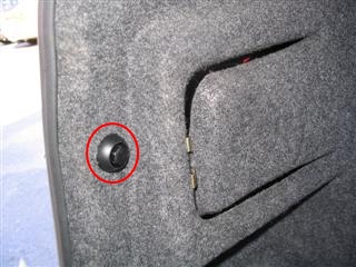 Figure 1.
The black screw nut needs to be removed
Figure 1.
The black screw nut needs to be removed
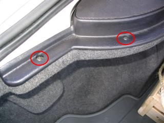 Figure
2. The Torx screws that need to be removed
Figure
2. The Torx screws that need to be removed
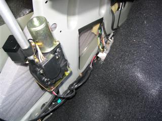 Figure 3. Electric antenna motor and
somewhere below it the CD changer connector
Figure 3. Electric antenna motor and
somewhere below it the CD changer connector
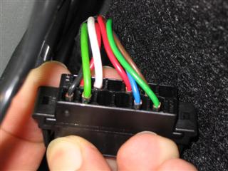 Figure
4. The CD changer connector
Figure
4. The CD changer connector
As an alternative, you can remove the Audio head unit and use the I-Bus signals of the head unit connector. The obvious drawback is that you don't see CAN messages sent by the Audio head unit. To get my CAN adapters connected to the CD changer connector I built a small connector adapter. I used a 9-pin D-sub female connector that had solderable pins, flat male pins from a connector that was laying around and some wire. The flat pins were just perfect so that they could be inserted in the CD changer connectors female sockets. The connector adapter is shown in Figure 5. I just wanted to keep the original connectors and wires intact, but you can also cut the wires and solder a D-sub connector along side the CD changer or any other connector that has the I-Bus signals.
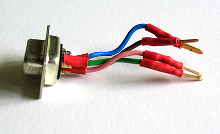 Figure 5. The small connector adapter
between the CD changer connector and CAN connector
Figure 5. The small connector adapter
between the CD changer connector and CAN connector
Electrical interface
I-Bus uses two (three) wires for communications: I+ and I- (plus ground). In standby (a recessive bit is sent) both I+ and I- signal measure 2,5 volts to ground. When a dominant bit is sent (the line goes active), the I+ signal goes up to 3,5 volts and the I- signal to 1,5 volts. So the difference between the I+ and I- signals increase from 0 volts to 2,0 volts.
CAN adapters
I have used three different CAN to PC adapters for the reverse-engineering. Well, actually I started the whole thing with a Microchip dsPIC evaluation kit that had a CAN interface, but I couldn't get it working, so I moved to ready made solutions. The first adapter was a small serial port connected adapter named CAN232 from LAWICEL AB, a Swedish company. The second was an USB connected adapter PCAN-USB from Peak Systems Technik. Finally I acquired a newer version of the CAN232, the CANUSB. It provides the an emulated RS232 interface, but also a Windows DLL interface. I've done several small programs using the CANUSB Windows drivers with success.
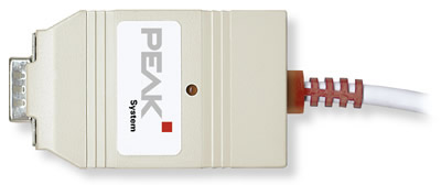 Figure
6. Peak-Systems Technik PCAN-USB adapter
Figure
6. Peak-Systems Technik PCAN-USB adapter
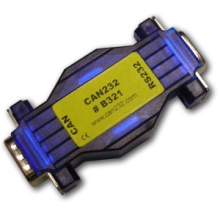 Figure 7.
Lawicel CAN232 adapter
Figure 7.
Lawicel CAN232 adapter
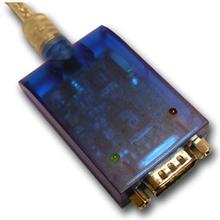 Figure 8. Lawicel
CANUSB adapter
Figure 8. Lawicel
CANUSB adapter
The advantage with the PCAN-USB adapter was the free Windows software PCAN-View Light that came with it. PCAN-View shows all the latest messages sent on the bus ordered by message ID. It has been a great help trying to figure out what bit or byte(s) correspond to a certain function (left back door open, engine rpm, ...). On the other hand, the CAN232 adapter is easy to use since it has a simple serial port interface. Also the CAN232 is much more affordable compared to the PCAN-USB. The CANUSB adapter costs a bit more than the CAN232, but I think it has much better features with still being cheaper than the PCAN-USB.
 Figure 9. PCANView Light program
showing I-Bus traffic
Figure 9. PCANView Light program
showing I-Bus traffic
The CAN adapters mainly use a 9-pin male D-sub connector for connecting to the CAN bus. In order to connect the adapter to the Saab I-Bus you must build a female D-sub connector that interfaces with the I-bus wires. The CAN232 adapter must be powered from the CAN connector, so you must have +12 V on pin 9. Both CAN232 and PCAN-USB adapters require ground on pin 3, I+ on pin 7 and I- on pin 2. You can see Figure 10 for the CiA (Can in Automation) pin assignment of the D-sub connector.
 Figure 10. CAN
adapter D-sub connector pin assignment according to CiA (image from CAN232.com)
Figure 10. CAN
adapter D-sub connector pin assignment according to CiA (image from CAN232.com)
Reverse-engineering the bus
After watching the communication with an oscilloscope I figured out that the CAN bus speed is 47,619 kbit/s (bit time is 21 µs). Well, to be frank, at first I rounded the bit times to 20 µs and got 50 kbit/s, which only generated receive errors. I've used bit timing register settings BTR0=07 BTR1=3F on my SJA1000 @ 16 MHz CAN controller chips. I got some receive errors on the CAN232, so those register settings needed some tweaking. Magnus Lirell then told me, that on his National Instruments PCMCIA CAN/2 card the working timer registers settings are BTR0=CB and BTR1=9A. After testing those settings myself, I've used them with success ever since. All the messages on the bus have eight (8) data bytes even if it wouldn't be necessary. I'm guessing this simplifies response time calculations and the software that receives and decodes the messages.
- CAN 2.0A (11-bit identifiers)
- Bus speed 47,619 kbit/s
- Timing register settings BTR0 0xCB, BTR1 0x9A
As an example the engine speed is located as a 16-bit integer value on message ID 460h (hexadecimal) in the second and third bytes (I define first byte as the most significant byte). Speed is in the same message in fourth and fifth bytes. The speed value is multiplied by ten, so you have to divide the 16-bit integer by 10 to get the real speed value.
Here's an example ID 460h message: 00 03 9C 00 2A 00 00 00
Engine rpm is 039Ch (hexadecimal format) = 924 (decimal format) = 942 RPM
Speed is 002Ah = 42 = 4,2 km/h
Discovered message information
220h - Trionic data initialization
This message must be sent before any queries to the Trionic can be sent. Trionic responds with a 238h message.| ID | Byte 0 | Byte 1 | Byte 2 | Byte 3 | Byte 4 | Byte 5 | Byte 6 | Byte 7 |
|---|---|---|---|---|---|---|---|---|
| 220h | 3Fh | 81h | 01h | 33h | 02h | 40h | 00h | 00h |
238h - Trionic data initialization reply
Trionic sends this message after a 220h message has been sent on the bus.| ID | Byte 0 | Byte 1 | Byte 2 | Byte 3 | Byte 4 | Byte 5 | Byte 6 | Byte 7 |
|---|---|---|---|---|---|---|---|---|
| 238h | 40h | BFh | 21h | C1h | 01h | 11h | 02h | 58h |
240h - Trionic data query
This message is sent as a command to the Trionic. It can be used to query "OBD-II" information. I use the quotation marks because basically this information is also available from the OBD-II interface. The problem with the OBD-II interface is that it's slow. By using directly the I-Bus (or even better, the P-Bus) you can achieve refresh rates 10 Hz...~50 Hz. The DATA byte below indicates what data is requested. The COMMAND byte is 01h for requesting OBD-II information. With COMMAND byte as 1Ah you can request information from the Trionic's software header. The header comprises of ASCII and hexadecimal data about e.g. Vehicle Identification Number (VIN), Immobilizer code, Software Saab part number, Hardware Saab part number and Software version string.| ID | Byte 0 | Byte 1 | Byte 2 | Byte 3 | Byte 4 | Byte 5 | Byte 6 | Byte 7 |
|---|---|---|---|---|---|---|---|---|
| 240h | 40h | A1h | 02h | COMMAND | DATA | 00h | 00h | 00h |
| DATA | Description | How to handle reply value |
|---|---|---|
| 00h | Some generic request (requires more research) | ? |
| 04h | Calculated load value | unit is % |
| 05h | Coolant temperature | subtract 40, unit °C |
| 0Bh | Manifold Air Pressure, MAP | unit hPa |
| 0Ch | Engine RPM | divide by 4, unit 1/min |
| 0Eh | Engine timing advance | ? |
| 0Fh | Intake air temperature | subtract 40, unit °C |
| 10h | Mass Air Flow, MAF | divide by 100, unit g/s |
| 14h | O2 sensor 1, Bank 1 | ? |
| 15h | O2 sensor 2, Bank 1 | ? |
| DATA | Description |
|---|---|
| 90h | Vehicle Identification Number, VIN |
| 91h | Hardware Saab part number |
| 92h | Immobilizer code |
| 94h | Software Saab part number |
| 95h | Software version |
| 97h | Engine type |
| 98h | Additional info |
| 99h | Software date |
258h - Trionic data query reply
Trionic sends these reply messages after receiving a 240h data query. There are several different ways the Trionic can respond. Below are three different ones. The ROW byte tells the row index of the reply (i.e. how many messages are still coming). It always seems to have the most significant bit, bit 7 set. Also, the first row has bit 6 set. So, a one line reply has a ROW byte of C0h, two line has ROW bytes C1h and 80h, three line has C2h, 81h, 80h, and so on. The LENGTH byte gives the length of the answer. However there's something a bit illogical about the LENGTH byte, since in the first response way detailed below, the LENGTH byte is either 03h or 04h. In the last response way LENGTH is logical, it tells the number of REPLY bytes plus two (5Ah and DATA byte). The last reply row is padded with 00h's if necessary.| ID | Byte 0 | Byte 1 | Byte 2 | Byte 3 | Byte 4 | Byte 5 | Byte 6 | Byte 7 |
|---|---|---|---|---|---|---|---|---|
| 258h | ROW | BFh | LENGTH | 41h | 00h | 00h | 00h | 00h |
| 258h | ROW | BFh | DATA | VALUE1 | [VALUE0] | 00h | 00h | 00h |
| ID | Byte 0 | Byte 1 | Byte 2 | Byte 3 | Byte 4 | Byte 5 | Byte 6 | Byte 7 |
|---|---|---|---|---|---|---|---|---|
| 258h | ROW | BFh | LENGTH | 41h | DATA | VALUE1 | [VALUE0] | 00h |
| ID | Byte 0 | Byte 1 | Byte 2 | Byte 3 | Byte 4 | Byte 5 | Byte 6 | Byte 7 |
|---|---|---|---|---|---|---|---|---|
| 258h | ROW | BFh | LENGTH | 5Ah | DATA | REPLY | REPLY | REPLY |
| 258h | ROW | BFh | REPLY | REPLY | REPLY | REPLY | REPLY | REPLY |
| 258h | ROW | BFh | REPLY | REPLY | REPLY | REPLY | REPLY | REPLY |
266h - Trionic reply acknowledgement
This message must be sent after every Trionic data query reply. Notice that bit 6 (which tells if this is the first reply row) of ROW byte is cleared in this acknowledgement message.| ID | Byte 0 | Byte 1 | Byte 2 | Byte 3 | Byte 4 | Byte 5 | Byte 6 | Byte 7 |
|---|---|---|---|---|---|---|---|---|
| 266h | 40h | A1h | 3Fh | ROW | 00h | 00h | 00h | 00h |
280h - Pedals, reverse gear
Message is sent with an interval of 1 second and if a value changes. The most significant bit of the first byte (byte 0) is set if information has changed from the last message. The GEAR byte is 02h if the reverse gear selected, otherwise the byte is FFh. When the brake pedal is pressed lightly only bit 1 of the PEDAL byte will be set. Normal braking will set bits 1, 3 and 4. The BRAKE/CLUTCH bit will also be set if the clutch is pressed. The ACTIVE bit in the CRUISE byte is set when cruise control has been activated. The ?? byte indicates that the engine is running or something like that (needs closer inspection).| ID | Byte 0 | Byte 1 | Byte 2 | Byte 3 | Byte 4 | Byte 5 | Byte 6 | Byte 7 |
|---|---|---|---|---|---|---|---|---|
| 280h | STATE | GEAR | PEDAL | - | CRUISE | ?? | - | - |
| Byte | Bit 7 | Bit 6 | Bit 5 | Bit 4 | Bit 3 | Bit 2 | Bit 1 | Bit 0 |
|---|---|---|---|---|---|---|---|---|
| STATE | CHANGED | - | - | - | - | - | - | - |
| PEDAL | - | - | KICKDOWN | BRAKE | BRAKE/CLUTCH | - | BRAKE | - |
| CRUISE | - | - | ACTIVE | - | - | - | - | - |
290h - Steering wheel and SID buttons
Message is sent with an interval of 1 second and if a value changes. The most significant bit of the first byte (byte 0) is set if information has changed from the last message. The audio button information and SID button information are duplicated to bytes 4 and 5.| ID | Byte 0 | Byte 1 | Byte 2 | Byte 3 | Byte 4 | Byte 5 | Byte 6 | Byte 7 |
|---|---|---|---|---|---|---|---|---|
| 290h | STATE | - | AUDIO | SID | AUDIO | SID | - | - |
| Byte | Bit 7 | Bit 6 | Bit 5 | Bit 4 | Bit 3 | Bit 2 | Bit 1 | Bit 0 |
|---|---|---|---|---|---|---|---|---|
| STATE | CHANGED | - | - | - | - | - | - | - |
| AUDIO | VOL- | VOL+ | SRC | SEEK+ | SEEK- | NXT | - | - |
| SID | CLR | SET | DOWN | UP | NPANEL | CLOCK+ | CLOCK- | - |
320h - Doors, central locking and seat belts
Message is sent with an interval of 1 second and if a value changes. The most significant bit of the first byte (byte 0) is set if information has changed from the last message. Bit LOCKED is 1 if doors are locked. Bit FL reports if the front left door is open, FR reports the same from the front right door (RL and RR bits indicate the rear doors). Bit TRUNK reports if the trunk is open. The BULBS byte indicates if there are any broken light bulbs, that the SID should report (Information provided by Magnus Lirell).| ID | Byte 0 | Byte 1 | Byte 2 | Byte 3 | Byte 4 | Byte 5 | Byte 6 | Byte 7 |
|---|---|---|---|---|---|---|---|---|
| 320h | STATE | DOOR | BELT | - | BULBS | - | - | - |
| Byte | Bit 7 | Bit 6 | Bit 5 | Bit 4 | Bit 3 | Bit 2 | Bit 1 | Bit 0 |
|---|---|---|---|---|---|---|---|---|
| STATE | CHANGED | - | - | - | - | - | - | - |
| DOOR | LOCKED | FL | FR | RL | RR | TRUNK | - | - |
| BELT | - | - | ?? | ?? | - | - | - | - |
| BULBS | - | Left park | - | - | - | - | - | - |
328h - SID audio text
A group of three messages are sent with an interval of 1 second and if a value changes. Messages are sent with about 10 milliseconds apart. The CHANGED bit in the ROW byte will be set if information changes. The two bits ORD0 and ORD1 in the ORDER byte are for sequence numbering. A new message group starts with the NEW bit set and both ORD0 and ORD1 bits. On the second message the NEW and ORD1 bits are cleared and the third message has also the ORD0 bit cleared. So the ORDER byte will be 42, 01 and 00 for the three sequential messages. The ROW byte tells to which row of the SID the text will be displayed on. The byte can have a value of 2 or 1, but in these audio text messages the row number is always 2. The TEXT4...TEXT0 bytes are plain ASCII coded characters that will be displayed on the SID.Note that the last message will contain only one normal character in the TEXT4 byte. The TEXT3 byte should contain a integer value that will be shown as a small number to indicate the selected radio station number. The last TEXT2...TEXT0 bytes are always zeros.
| ID | Byte 0 | Byte 1 | Byte 2 | Byte 3 | Byte 4 | Byte 5 | Byte 6 | Byte 7 |
|---|---|---|---|---|---|---|---|---|
| 328h | ORDER | - | ROW | TEXT4 | TEXT3 | TEXT2 | TEXT1 | TEXT0 |
| Byte | Bit 7 | Bit 6 | Bit 5 | Bit 4 | Bit 3 | Bit 2 | Bit 1 | Bit 0 |
|---|---|---|---|---|---|---|---|---|
| ORDER | - | NEW | - | - | - | - | ORD1 | ORD0 |
| ROW | CHANGED | - | - | - | - | - | ROW1 | ROW0 |
32Ch - ACC to SID text
This message is identical to the 32Fh message. The only difference is that this message is sent by the ACC (Automatic Climate Control).
32Fh - TWICE to SID text
This SID full-screen text message is almost identical to the previous 328h SID audio text message. This 32Fh message is used by the TWICE (Theft Warning Integrated Central Electronics) to display text on the SID. The row number can be one in this message. And the ORDER byte contains an ORD2 bit so that six messages can be sent. Also the last three bytes of messages #3 and #6 (that's with ORDER bytes 03h and 06h) are 20h, not 00h like in the audio text message.
Example message group: The texts "2 REMOTE KEY" and "2 TRANSPONDR" will be displayed on rows one and two of the SID display.337h - SPA to SID text
This message is identical to the previous 32Fh message. The only difference is that this message is sent by the SPA (Saab Park Assist).
348h - SID audio text control
Message is sent with an interval of 1 second. The normal value (i.e. don't display text) of byte STATUS is FFh. When a 328h SID audio text message group is sent, the STATUS byte is changed to 04h and immediately after that to 05h for the duration of the messages. After the 328h messages, the status byte returns to FFh.
Notice that the control messages use a 20h increment relative to the actual text messages in their IDs. Bytes 0 and 3 probably have something to do with priority (which text is displayed if several texts should be displayed at the same time).
| ID | Byte 0 | Byte 1 | Byte 2 | Byte 3 | Byte 4 | Byte 5 | Byte 6 | Byte 7 |
|---|---|---|---|---|---|---|---|---|
| 348h | 11 | 02 | STATUS | 19 | 00 | 00 | 00 | 00 |
34Ch - ACC to SID text control
Message is sent with an interval of 1 second. The normal value of byte STATUS is FFh. When a 32Ch ACC to SID text message group is sent, the STATUS byte changes between 03h and 05h for the duration of the messages. After the 32Ch messages, the status byte returns to FFh. Byte UNKNOWN1 seems to stay at 00h and UNKNOWN2 byte at 23h.
| ID | Byte 0 | Byte 1 | Byte 2 | Byte 3 | Byte 4 | Byte 5 | Byte 6 | Byte 7 |
|---|---|---|---|---|---|---|---|---|
| 34Ch | 18 | UNKNOWN1 | STATUS | UNKNOWN2 | 00 | 00 | 00 | 00 |
34Fh - TWICE to SID text control
Message is sent with an interval of 1 second. The normal value of byte STATUS is FFh. When a 32Fh TWICE to SID text message group is sent, the STATUS byte is changed to 04h and immediately after that to 05h for the duration of the messages. After the 32Fh messages, the status byte returns to FFh.| ID | Byte 0 | Byte 1 | Byte 2 | Byte 3 | Byte 4 | Byte 5 | Byte 6 | Byte 7 |
|---|---|---|---|---|---|---|---|---|
| 34Fh | 1B | 00 | STATUS | 2D | 00 | 00 | 00 | 00 |
357h - SPA to SID text control
Message is sent with an interval of 1 second. The normal value of byte STATUS is FFh. When a 337h SPA to SID text message group is sent, the STATUS byte is changed to 04h and immediately after that to 05h for the duration of the messages. After the 337h messages, the status byte returns to FFh. Byte UNKNOWN1 is 00h when STATUS is FFh and 01h when STATUS is 05h. UNKNOWN2 byte also changes from 08h (STATUS is FFh) to 12h (STATUS is 05h).| ID | Byte 0 | Byte 1 | Byte 2 | Byte 3 | Byte 4 | Byte 5 | Byte 6 | Byte 7 |
|---|---|---|---|---|---|---|---|---|
| 357h | 1F | UNKNOWN1 | STATUS | UNKNOWN2 | 00 | 00 | 00 | 00 |
368h - SID text priority
Message is sent with an interval of 1 second and if a value changes. Message is sent in a group of three messages. The first byte, ROW, has the values 0h, 1h, 2h corresponding to lines on the SID. The 0h line needs more research, since as you know the SID has only two lines of text it can display. If the PRIORITY byte is FFh, there is nothing shown on the SID. However, when a control unit sends text messages (e.g. messages 337h and 357h), its requested priority is shown on the PRIORITY byte. If another control unit wants to override the currently shown text message, it needs to send messages with a higher priority, i.e. with a lower PRIORITY byte value.
| ID | Byte 0 | Byte 1 | Byte 2 | Byte 3 | Byte 4 | Byte 5 | Byte 6 | Byte 7 |
|---|---|---|---|---|---|---|---|---|
| 368h | ROW | PRIORITY | - | - | - | - | - | - |
380h - Audio RDS status
Message is sent with an interval of 1 second and if a value changes. This message tells the RDS status of the Audio system.
| ID | Byte 0 | Byte 1 | Byte 2 | Byte 3 | Byte 4 | Byte 5 | Byte 6 | Byte 7 |
|---|---|---|---|---|---|---|---|---|
| 380h | STATE | UNKNOWN | STATUS | - | - | - | - | - |
| Byte | Bit 7 | Bit 6 | Bit 5 | Bit 4 | Bit 3 | Bit 2 | Bit 1 | Bit 0 |
|---|---|---|---|---|---|---|---|---|
| STATE | CHANGED | - | - | - | - | - | - | - |
| STATUS | RDS activ. | No TP signal | ?? | TP activ. | PTY activ. | ?? | ?? | No RDS signal |
3B0h - Head lights
Message is sent with an interval of 1 second and if a value changes. The most significant bit of the first byte (byte 0) is set if information has changed from the last message. LIGHT byte indicates the park and daylight head-lights with the PARK and DAY bits. When ignition signal is off, the OFF bit is set in the LIGHT byte. The ?? byte is 20h when ignition signal is off and B8h when the signal is on.| ID | Byte 0 | Byte 1 | Byte 2 | Byte 3 | Byte 4 | Byte 5 | Byte 6 | Byte 7 |
|---|---|---|---|---|---|---|---|---|
| 3B0h | STATE | LIGHT | - | ?? | - | - | - | - |
| Byte | Bit 7 | Bit 6 | Bit 5 | Bit 4 | Bit 3 | Bit 2 | Bit 1 | Bit 0 |
|---|---|---|---|---|---|---|---|---|
| STATE | CHANGED | - | - | - | - | - | - | - |
| LIGHT | - | 1 | 1 | 1 | OFF | 1 | PARK | DAY |
| ?? | - | - | - | - | - | - | - | - |
3C0h - CD Changer control
Message is sent with an interval of 1 second. The most significant bit of the first byte, CHANGED, indicates when information has changed in the message. Byte 1, COMMAND, specifies what CD Changer controlling button has been pressed. The PARAM byte is used by "Change to CD" command to inform which CD was selected.| ID | Byte 0 | Byte 1 | Byte 2 | Byte 3 | Byte 4 | Byte 5 | Byte 6 | Byte 7 |
|---|---|---|---|---|---|---|---|---|
| 3C0h | CHANGED | COMMAND | PARAM | - | - | - | - | - |
| COMMAND | Description |
|---|---|
| 59h | Next (NXT button) |
| 35h | Seek next (Seek+) |
| 36h | Seek previous (Seek-) |
| 68h | Change to CD according to PARAM byte |
| B0h | Audio mute (off?) |
| B1h | Audio mute (on?) |
| 76h | Random play (long press of CD/RDM button) |
3C8h - CD Changer information
Message is sent with an interval of 1 second. The most significant bit of the first byte, CHANGED, indicates when information has changed in the message. MAGAZINE byte informs which disc slots are occupied and which are empty. The lower nibble of DISC byte (DISC3...DISC0) tells which CD disc is being played in BCD coding. TRACK byte tells the track number being played in BCD coding. The bytes MIN and SEC tell the play minutes and seconds of the current track, also in BCD coding. When there's no disc in play, the TRACK, MIN and SEC bytes are FFh. The STAT0...STAT2 bits indicate the status of the CD changer. If the STAT value is 0h, the CD changer is inactive (not spinning). Value 3h means power-up / spin-up, but not ready yet. And value 4h means that everything is OK - playing disc.
SECURITY byte informs the Audio head unit if the CD Changer has not been married or is married to a different car. If the byte is D0h, everything is alright. Values 50h and 10h mean that the CD Changer needs to be married to the car (text "CDC CODE" will be displayed on SID). Value 90h means the CD Changer has been married to a different car and the VIN doesn't correspond to the one stored in the CD Changer (text "CDC LOCKED" will be display on SID).
| ID | Byte 0 | Byte 1 | Byte 2 | Byte 3 | Byte 4 | Byte 5 | Byte 6 | Byte 7 |
|---|---|---|---|---|---|---|---|---|
| 3C8h | CHANGED | - | MAGAZINE | DISC | TRACK | MIN | SEC | SECURITY |
| Byte | Bit 7 | Bit 6 | Bit 5 | Bit 4 | Bit 3 | Bit 2 | Bit 1 | Bit 0 |
|---|---|---|---|---|---|---|---|---|
| CHANGED | CHANGED | - | ?? | - | - | - | - | - |
| MAGAZINE | - | - | CD6 | CD5 | CD4 | CD3 | CD2 | CD1 |
| DISC | - | STAT2 | STAT1 | STAT0 | DISC3 | DISC2 | DISC1 | DISC0 |
3E0h - Automatic Gearbox
Message is sent with an interval of 1 second and if a value changes. The most significant bit of the first byte (byte 0) is set if information has changed from the last message. The GEAR byte indicates in what state the gearbox is. Value 05h means Forward, value 03h Neutral and value 02h Reverse. The GEAR SHIFT byte tells in what position the gear shift is. Value 01h means Park, value 02h Reverse, value 03h Neutral, value 04h Drive, value 08h "limit to 4", value 07h "limit to 3" and value 06h "low speed gear".
| ID | Byte 0 | Byte 1 | Byte 2 | Byte 3 | Byte 4 | Byte 5 | Byte 6 | Byte 7 |
|---|---|---|---|---|---|---|---|---|
| 3E0h | STATE | GEARBOX | GEAR SHIFT | MODE1 | Adaptation? | MODE2 | - | - |
| Byte | Bit 7 | Bit 6 | Bit 5 | Bit 4 | Bit 3 | Bit 2 | Bit 1 | Bit 0 |
|---|---|---|---|---|---|---|---|---|
| STATE | CHANGED | - | - | - | - | - | - | - |
| GEARBOX | - | - | - | - | - | - | - | - |
| GEAR SHIFT | - | - | - | - | POS | POS | POS | POS |
| MODE2 | - | - | - | - | - | - | SPORT/WINTER | SPORT/WINTER |
410h - Light dimmer and light sensor
Message is sent with an interval of 1 second and if a value changes. The most significant bit of the first byte (byte 0) is set if information has changed from the last message. DIMM1 and DIMM0 form a 16-bit integer for instrumentation panel dimmer position. Integer value is between about 4600h and FD00h. LIGHT1 and LIGHT0 form also a 16-bit integer for the SID light sensor. Typical values range from about 1800h to 2C00h. The NPANEL byte indicates if the Night Panel function is on (Information provided by Magnus Lirell).| ID | Byte 0 | Byte 1 | Byte 2 | Byte 3 | Byte 4 | Byte 5 | Byte 6 | Byte 7 |
|---|---|---|---|---|---|---|---|---|
| 410h | STATE | DIMM1 | DIMM0 | LIGHT1 | LIGHT0 | NPANEL | - | - |
| Byte | Bit 7 | Bit 6 | Bit 5 | Bit 4 | Bit 3 | Bit 2 | Bit 1 | Bit 0 |
|---|---|---|---|---|---|---|---|---|
| STATE | CHANGED | - | - | - | - | - | - | - |
430h - SID beep request
This message is sent when the SID is requested to beep (what unit sends this request is still unknown).
| ID | Byte 0 | Byte 1 | Byte 2 | Byte 3 | Byte 4 | Byte 5 | Byte 6 | Byte 7 |
|---|---|---|---|---|---|---|---|---|
| 430h | 80 | 04 | 00 | 00 | 00 | 00 | 00 | 00 |
439h - SPA distance
Message is sent with an interval of ??. The DIST byte indicates the distance to objects behind the car according to the SPA (Saab Park Assist).
| ID | Byte 0 | Byte 1 | Byte 2 | Byte 3 | Byte 4 | Byte 5 | Byte 6 | Byte 7 |
|---|---|---|---|---|---|---|---|---|
| 439h | STATE | - | DIST | - | - | - | - | - |
460h - Engine rpm and speed
Message is sent with an interval of 100 milliseconds. The ENGOFF bit of the first ENG byte indicates if the engine is off (the bit is 0 when engine is on). RPM1 and RPM0 form a 16-bit integer for engine speed (in RPM). Integer value is between 0000h and 1B00h. SPD1 and SPD0 form also a 16-bit integer for the car speed. The unit for the value is 100 meters per hour, so in order to get speed in kilometers per hour you must divide the integer value by ten.| ID | Byte 0 | Byte 1 | Byte 2 | Byte 3 | Byte 4 | Byte 5 | Byte 6 | Byte 7 |
|---|---|---|---|---|---|---|---|---|
| 460h | ENG | RPM1 | RPM0 | SPD1 | SPD0 | - | - | - |
| Byte | Bit 7 | Bit 6 | Bit 5 | Bit 4 | Bit 3 | Bit 2 | Bit 1 | Bit 0 |
|---|---|---|---|---|---|---|---|---|
| ENG | ENGOFF | - | - | - | - | - | - | - |
4A0h - Steering wheel, Vehicle Identification Number
Message is sent with an interval of 1 second and if a value changes. The most significant bit of the first byte (byte 0) is set if information has changed from the last message. The WIPER byte indicates the position of the windshield wiper control. The least significant bit of the WIPER byte indicates that the park lights are on. The LEFT and RIGHT bits of the SIGNAL byte indicate if a signal light is on. So when the signal light blinks, so does the bits. The REARFOG bit indicates if the rear fog light is on.
Vehicle Identification Number, VIN, is transmitted on bytes 4...6 (VIN2...VIN0). To be more precise, the car serial number part of the VIN is transmitted. It is coded so that the last number of the VIN, which probably is a checksum, is moved to the upper part of the first (VIN2) byte. For example if your VIN is YS3DC55C612123456, your serial number part is that in bold, 123456. The last number, 6, is the checksum number. Moving it to the upper part of the VIN2 byte, the VIN bytes would be VIN2 = 61h, VIN1 = 23h, VIN0 = 45h.
| ID | Byte 0 | Byte 1 | Byte 2 | Byte 3 | Byte 4 | Byte 5 | Byte 6 | Byte 7 |
|---|---|---|---|---|---|---|---|---|
| 4A0h | STATE | WIPER | SIGNAL | - | VIN2 | VIN1 | VIN0 | - |
| Byte | Bit 7 | Bit 6 | Bit 5 | Bit 4 | Bit 3 | Bit 2 | Bit 1 | Bit 0 |
|---|---|---|---|---|---|---|---|---|
| STATE | CHANGED | - | - | - | - | - | - | - |
| WIPER | - | DRIZZLE | NORMAL | BACK | - | - | - | PARK |
| SIGNAL | - | - | - | - | - | LEFT | RIGHT | REARFOG |
520h - ACC, inside temperature
Message is sent with an interval of 1 second. Inside temperature is reported with the 8-bit byte TEMP. In order to get the correct temperature, the value must be subtracted with 40. This is done to encode negative temperatures. So a value of 58 (3Ah) is in fact +18 degrees Celsius and on the other hand a value of 29 (1Dh) would give an temperature of -11 degrees Celsius. The REARHEAT bit in the ACC byte indicates if the rear window heater is on.| ID | Byte 0 | Byte 1 | Byte 2 | Byte 3 | Byte 4 | Byte 5 | Byte 6 | Byte 7 |
|---|---|---|---|---|---|---|---|---|
| 520h | - | ACC | - | - | - | TEMP | - | - |
| Byte | Bit 7 | Bit 6 | Bit 5 | Bit 4 | Bit 3 | Bit 2 | Bit 1 | Bit 0 |
|---|---|---|---|---|---|---|---|---|
| ACC | - | REARHEAT | - | - | - | - | - | - |
530h - ACC
Message is sent with an interval of 1 second. The ACCON bit in the ACC byte tells if the ACC (Automatic Climate Control) is turned on. When the bit is set, the ACC is on and when the bit is cleared the ACC has been turned off. ACPRESS byte shows the A/C Pressure (unit is bar).| ID | Byte 0 | Byte 1 | Byte 2 | Byte 3 | Byte 4 | Byte 5 | Byte 6 | Byte 7 |
|---|---|---|---|---|---|---|---|---|
| 530h | - | ACC | - | ACPRESS | - | - | - | - |
| Byte | Bit 7 | Bit 6 | Bit 5 | Bit 4 | Bit 3 | Bit 2 | Bit 1 | Bit 0 |
|---|---|---|---|---|---|---|---|---|
| ACC | - | - | - | - | - | ACCON | - | - |
590h - Position Seat Memory
Message is sent with an interval of 1 second and if a value changes. The most significant bit of the first byte (byte 0) is set if information has changed from the last message.
| ID | Byte 0 | Byte 1 | Byte 2 | Byte 3 | Byte 4 | Byte 5 | Byte 6 | Byte 7 |
|---|---|---|---|---|---|---|---|---|
| 590h | STATE | MEM | - | - | - | - | - | - |
| Byte | Bit 7 | Bit 6 | Bit 5 | Bit 4 | Bit 3 | Bit 2 | Bit 1 | Bit 0 |
|---|---|---|---|---|---|---|---|---|
| STATE | CHANGED | - | - | - | - | - | - | - |
| MEM | - | - | - | - | - | STORE | MEM1 | MEM0 |
5C0h - Coolant temperature, air pressure
Message is sent with an interval of 1 second. Temperature is reported with a 8-bit byte. In order to get the correct coolant temperature, the value must be subtracted with 40. This is done to encode negative temperatures. So a value of 58 (3Ah) is in fact +18 degrees Celsius and on the other hand a value of 29 (1Dh) would give an temperature of -11 degrees Celsius. The 16-bit value combined from PRES1 and PRES0 gives the Ambient air pressure in hehtopascals [hPa].| ID | Byte 0 | Byte 1 | Byte 2 | Byte 3 | Byte 4 | Byte 5 | Byte 6 | Byte 7 |
|---|---|---|---|---|---|---|---|---|
| 5C0h | - | COOLANT | PRES1 | PRES0 | - | - | - | - |
630h - Fuel usage
Message is sent with an interval of 1 second. Fuel usage since last start is reported with an 16-bit integer value (bytes FUEL1...FUEL0). The FUEL1 byte is the most significant byte. The unit is milliliters of fuel (used since start). The amount of fuel left in the tank is indicated by 16-bit integer values AVGTANK and TANK. The TANK value seems to be a raw measurement value and the AVGTANK an averaged value of the raw measurements. A full tank is about 02A0h and a soon empty tank below 0040h. Dividing the value by 10 could give the available fuel amount in liters (this is a guess). The first byte VALID at least informs if the tank values should be disregarded. For example during a engine start the two least significant bits (TANKVALID) are set, meaning that the AVGTANK and TANK values are not correct (they seem to be zeros).| ID | Byte 0 | Byte 1 | Byte 2 | Byte 3 | Byte 4 | Byte 5 | Byte 6 | Byte 7 |
|---|---|---|---|---|---|---|---|---|
| 630h | VALID | FUEL1 | FUEL0 | AVGTANK1 | AVGTANK0 | TANK1 | TANK0 | - |
| Byte | Bit 7 | Bit 6 | Bit 5 | Bit 4 | Bit 3 | Bit 2 | Bit 1 | Bit 0 |
|---|---|---|---|---|---|---|---|---|
| VALID | - | - | - | - | ?? | ?? | TANKVALID | TANKVALID |
640h - Mileage
Message is sent with an interval of 1 second. Mileage is reported with an 24-bit integer value (bytes MIL2...MIL0). The unit is 10 meters, so in order to get the mileage in kilometers the value must be divided by a hundred.| ID | Byte 0 | Byte 1 | Byte 2 | Byte 3 | Byte 4 | Byte 5 | Byte 6 | Byte 7 |
|---|---|---|---|---|---|---|---|---|
| 640h | - | - | MIL2 | MIL1 | MIL0 | - | - | - |
6A1h - Audio head unit
The Audio head unit uses messages with ID 6A1h to communicate with the CD changer. Byte 3 seems to be the command for the CD changer. Value 13h is power-up / spin-up, value 12h play and 18h power-down / spin-down.
| ID | Byte 0 | Byte 1 | Byte 2 | Byte 3 | Byte 4 | Byte 5 | Byte 6 | Byte 7 |
|---|---|---|---|---|---|---|---|---|
| 6A1h | 21 | 00 | 00 | COMMAND | 01 | ?? | ?? | - |
6A2h - CD changer
The CD changer uses messages with ID 6A2h to communicate with the Audio head unit.
| ID | Byte 0 | Byte 1 | Byte 2 | Byte 3 | Byte 4 | Byte 5 | Byte 6 | Byte 7 |
|---|---|---|---|---|---|---|---|---|
| 6A2h | - | - | - | - | - | - | - | - |
720h - RDS time
Message is sent with an interval of 1 second. The RDSON byte indicates if a RDS signal has been detected.
| ID | Byte 0 | Byte 1 | Byte 2 | Byte 3 | Byte 4 | Byte 5 | Byte 6 | Byte 7 |
|---|---|---|---|---|---|---|---|---|
| 720h | - | SEC | MIN | HOUR | DAY | MONTH | RDSON | - |
730h - Clock
Message is sent with an interval of 8 seconds. The ENGCOLD byte indicates how many minutes has passed since the ignition was turned off.| ID | Byte 0 | Byte 1 | Byte 2 | Byte 3 | Byte 4 | Byte 5 | Byte 6 | Byte 7 |
|---|---|---|---|---|---|---|---|---|
| 730h | - | SEC | MIN | HOUR | DAY | MONTH | ENGCOLD | - |
740h 750h - Security
Messages are sent when the car key is turned to ignition on. This leads me to believe that these two messages are somehow connected to the anti-theft system. The CODE bytes seem to have random numbers in them that change after a successful "handshake".
The 750h message is sent first and after about 20 ms the 740h message is sent. The "reply" can contain zeroed CODE bytes and the STATUS byte as FFh. In that case after about 190 ms the same 750h message is repeated. The second 740h "reply" seems to be always ok, since it has something in the CODE bytes and the STATUS byte is 55h.
| ID | Byte 0 | Byte 1 | Byte 2 | Byte 3 | Byte 4 | Byte 5 | Byte 6 | Byte 7 |
|---|---|---|---|---|---|---|---|---|
| 740h | CODE4? | CODE3? | CODE2? | CODE1? | CODE0? | STATUS | 00 | 00 |
| 750h | CODE4? | CODE3? | CODE2? | CODE1? | CODE0? | 00 | 00 | 00 |
7A0h - Outside temperature
Message is sent with an interval of 1 second. There are two temperature values: AVGTEMP and RAWTEMP. AVGTEMP is the averaged outside temperature with a reading accuracy of 1 degree Celsius. The other temperature, RAWTEMP, shows the raw temperature readings. It has a reading accuracy of 0.5 degrees Celsius. Temperatures are reported as 16-bit values. In order to get the correct temperature, the value must be divided by 10 and subtracted with 40. In other words, a value of 0235h is first converted to decimal, 565, then divided by 10, so that we get 56.5 and finally subtract 40 to get 16.5 degrees Celsius. The STATUS byte most likely tells if the temperature readings are inside or outside values. The SID seems to display the inside temperature for some time. During this time the STATUS byte is 30h. After the a while the STATUS bytes changes to first to 80h and then right after to 00h. This probably means that the temperature readings are outside values.| ID | Byte 0 | Byte 1 | Byte 2 | Byte 3 | Byte 4 | Byte 5 | Byte 6 | Byte 7 |
|---|---|---|---|---|---|---|---|---|
| 7A0h | STATUS | AVGTEMP1 | AVGTEMP0 | RAWTEMP1 | RAWTEMP0 | - | - | - |
Example program
Introduction
I haven't got much experience in Windows programming, so I used Visual Basic .NET to create a little example program. The program listens to the serial port for CAN frames sent from the CAN232 adapter. For sake of simplicity I didn't do any initialization code for the adapter, so the user must first initialize it and open the CAN channel in the adapter (enabling incoming CAN frames). So it's bit of a pain to use, but does demonstrate how to visualize the received CAN messages. You can see a screenshot of the program in Figure 11.
 Figure
11. Main window of the Visual Basic .NET example program.
Figure
11. Main window of the Visual Basic .NET example program.
Source code
You can freely download the source code:The compiled executable file has been included, but you can compile it for yourself if you have the Visual Basic .NET development environment. You must also install the Microsoft .NET Framework, if you haven't done so yet. You can find the framework on Microsoft's site: Microsoft .NET Framework Version 1.1 Redistributable Package or by using the Microsoft Windows Update. Note that there are some known bugs in the example program, that I haven't had time to fix yet. Mainly the Clutch Pedal indication does not work correctly.
Requirements
- Microsoft Windows 2000/XP
- Microsoft .NET Framework
- Lawicel CAN232 adapter (configured at 57600 baud)
- A connector adapter to get CAN232 connected to the Saab I-Bus
- Serial port COM2 available for CAN232
- Terminal program for configuring the CAN232
Usage
First of all connect your CAN232 adapter to the I-Bus and remember to have it powered from the CAN D-sub connector. My program works with serial port COM2, so you need to compile the program with different settings if COM2 is not available to you. Launch the Saab 9-3 I-Bus Explorer and a terminal application (Microsoft HyperTerminal, TeraTerm, etc.). In the terminal use settings 57600 baud, 8 data bytes, 1 stop byte, no parity (if you haven't changed CAN232's baud settings). If you have changed the baud setting to something different than 57600, you must change it back or recompile with your own setting. Now before you can press the Open button on the I-Bus Explorer, you must issue in the terminal application the following commands.
[CR]
V[CR] (optional)
X1[CR] (saved to memory, need to issue only once for an adapter)
sCB9A[CR]
O[CR]
A little explanation might be in order. First of all press Enter (Carriage Return) once or twice. This is to flush the CAN232's input receive buffer. Then write the capital V and press enter. If you have the correct serial communications settings setup, the device should return it's hardware and software version. This is only to insure you have the right settings, you can skip the version checking if you want. If you haven't enabled Auto Poll/Send mode, you need to issue the X1 command (that's X-ray One, not X-ray Lima). Once you have done this (enabled the mode), it's saved to non-volatile memory and you don't have to issue it again. The most important command is setting the bit timing registers with the sCB9A command. Finally open the CAN channel with the O command (that's Oscar, not Zero). Your terminal should now start flooding with CAN messages if everything is working (there might not be any traffic on the bus, try to turn the ignition key or open central locking).
For more information about the terminal commands issued, refer to the CAN232 Manual [6].
OBD2SID - OBD-II information to SID
Introduction
OBD2SID is a Windows console application that uses CANUSB to connect to the Saab I-Bus, fetch information from the Trionic ECU and display values on the Saab Information Display, SID. You basically have to have a laptop (or similar) in your car, with the CANUSB adapter connected to the I-Bus. The console application reads messages on the bus and transmits messages to get text on the SID.
Note that this is a proof-of-concept application, and if possible, you should make it better or re-write it totally. I have also some ideas about showing Diagnostic Trouble Codes on the SID with the application, but with limited time, it may take a while before I do an update. You can watch a demonstration of how the application works from a video I made: OBD-II info to Saab 9-3 SID (hosted on YouTube).
 Figure 12.
Screenshot of OBD2SID application running.
Figure 12.
Screenshot of OBD2SID application running.
Source code
I used Bloodshed Dev-C++ v4.9.9.2 to compile the application. It should compile with other compilers, but I haven't tested it. You need to check the variable sizes if you intend to port it to a new platform.
You can download the application (source code included) here:Requirements
- Microsoft Windows
- Lawicel CANUSB adapter
- A connector adapter to get CANUSB connected to the Saab I-Bus
Usage
Plug the CANUSB adapter to your laptop and connect it to the Saab I-Bus - your now ready to just run the application. Hit any key to exit.
SaabCanLogger
Introduction
I couldn't find a simple free CAN bus logging application to suit my needs, so I wrote one myself. SaabCanLogger simply logs all received CAN messages to a text file from either the I-Bus or P-Bus. It currently only supports the Lawicel CANUSB. Figure 13 shows an example how simple to use the application is.
 Figure 13. Screenshot of SaabCanLogger session.
Download
I used Bloodshed Dev-C++ v4.9.9.2 to compile the application. It should compile with other compilers, but I haven't tested it. You need to check the variable sizes if you intend to port it to a new platform.
You can download the application (source code included) here:Comments, questions?
Contact information
If you have comments, questions, new decoded I-Bus messages or would like to share information about your own Saab I-Bus project, you're free to email me at firstname.surname@gmail.com. Note that you have to fix the email address, the one in the link is invalid (firstname = tomi and surname = liljemark). It may take me sometime to answer, but I'll try to answer everyone.
Frequently Asked Questions
References
- Wikipedia, the free encyclopedia: Controller Area Network (HTML document)
- Nilsson, Staffan: Controller Area Network - CAN Information (HTML document)
- Can in Automation CiA: CAN physical layer (HTML document)
- Kvaser AB: The CAN Protocol (HTML document)
- Kvaser AB: CAN Physical Layers (HTML document)
- Lawicel: CAN232 Manual (PDF document)